handle signal routing in flexible PCBs
When it comes to high-speed signal routing in flexible PCBs, it is important to be aware of and address the various signal integrity issues that may arise. These issues can cause data corruption and reduce the overall performance of electronic systems. Fortunately, proper design and simulation can mitigate these issues, eliminating costly physical prototyping iterations and resulting in reliable, high-speed systems.
Signal routing over a different reference plane can cause crosstalk, which can result in distortions and loss of signal strength. To avoid this, engineers should route signals over a single plane as much as possible and minimize bending of the circuit board.
The choice of substrate material can also have a major impact on signal integrity. Different materials have varying dielectric constants and loss tangents, which can influence signal propagation and attenuation. For example, materials with lower dielectric constants have a greater ability to carry high-speed signals, which can decrease the probability of data corruption and increase system performance.
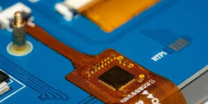
How do you handle signal routing in flexible PCBs?
It is also advisable to use symmetrical routing of differential signal lines to ensure consistent impedance, and to avoid sharp corners and right-angle bends in the signals. This will help to decrease signal reflections and impedance fluctuations, reducing noise and signal skew. It is also recommended to use a decoupling capacitor near power pins to prevent voltage fluctuations from impacting the signal quality.
The selection of the right copper foil is important for flexible pcb that are designed to bend and move. For flex circuits that are subject to repeated creasing and movement, engineers should choose rolled annealed (RA) copper rather than unannealed. RA copper is more resilient in the Z direction and can stretch much further before fatigue cracking occurs.
A flexible PCB that requires a number of layers or has large gaps between components can be reinforced with stiffeners to make it more rigid and able to withstand bending. However, this will add to the cost of the circuit board.
Another important consideration for flex circuits is the placement of vias. It is a good idea to use back-drilling techniques to remove unused portions of the via and improve signal transmission. Additionally, it is important to limit the density of vias in high-speed signal paths to avoid compromising the signal integrity.
Flexible PCBs are also expected to play a critical role in the advancement of 5G technology. The deployment of 5G networks requires highly integrated and compact electronics capable of operating at high frequencies. Flexible PCBs, with their ability to support complex, high-density circuit designs, are well-suited for use in 5G antennas, modules, and other critical components.
Lastly, it is important to separate the analog and digital ground planes to prevent the potential for interference between traces. In addition, it is a good idea to avoid placing any high-speed signal wires within the mesh ground planes as these can radiate electromagnetic interference (EMI) into the adjacent layer. A solid ground plane should be used instead of a mesh ground plane to protect the sensitive signals from EMI.