
Rigid Flex PCB Without Damaging Components
Rigid flex has revolutionized the electronics industry, allowing for compact and flexible electronic devices. These PCBs can be bent and twisted to fit into tight spaces or to conform to irregular shapes, which is crucial in a number of applications, including wearable technology and medical devices. While rigid flex offers distinct advantages, it also presents unique design challenges that require careful deliberation and mastery to overcome. One of the most critical factors in determining the bending limits of rigid-flex circuit boards is the bending radius. This limit determines how tightly a rigid-flex circuit board can bend without causing damage to copper traces, ground planes, and components. Considering the bending radius when designing a rigid-flex circuit board will help ensure the product’s reliability, durability, and functionality.
The bending radius of a rigid-flex PCB is determined by the thickness of the plate, as well as the number of layers it has. Thicker plates typically have a greater minimum bending radius, since they are more rigid than thinner plates. The number of layers also influences the bending radius, since each additional layer increases the rigidity of the board.
It is essential to consider the bending radius when designing a rigid-flex PCB, as failure to adhere to these guidelines can result in a number of mechanical complications, including signal degradation and signal loss. In addition, the bending radius may impact the ability of the PCB to withstand high-vibration applications and long-term flexing, which can shorten the lifespan of the device.
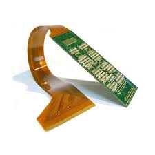
How to Design a Rigid Flex PCB Without Damaging Components
To ensure a rigid-flex PCB can bend without causing damage, it is necessary to incorporate sufficient strain relief features into the design. These include teardrop-shaped pads, rounded corners, and extra material in areas of the board that are most likely to be exposed to stress. This helps distribute the mechanical stress evenly, preventing stress concentration points that can lead to premature PCB failure.
In addition to implementing adequate strain relief features, it is important to stagger traces on a rigid-flex PCB. Staggered traces will minimize the risk of shorts, which can be caused by stress on the PCB during flexing or bending. It is also beneficial to use a thin coverlay to reduce the chances of oxidation, which can damage the copper traces and components on a rigid-flex circuit board.
Choosing the right materials for both the rigid and flexible portions of a rigid-flex PCB is also vital. Different materials have varying thermal expansion rates, which can cause impedance disruptions and signal integrity problems when the PCB is subjected to temperature fluctuations. In addition, proper connector placement is key to ensuring that the transition between the rigid and flexible sections of the PCB does not cause mechanical stress or other problems. Taking these precautions will allow rigid-flex circuit boards to withstand rigorous applications and prolonged flexing without sustaining any damage or failure.